ISO code of turning inserts: how to read CNMG 120408
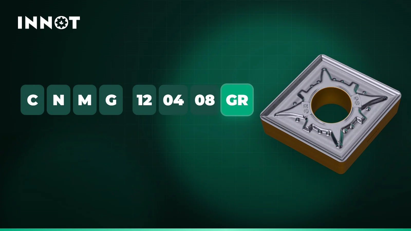
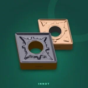
Every turning insert has an ISO designation that describes its shape and size: if you can read it, you choose the right insert in seconds and know immediately whether it fits the toolholder already on your machine. Let’s take one of the most widely used inserts as an example, the CNMG 120408-GR.
1. Insert shape
The first letter gives the shape and therefore the point angle. The larger the angle, the stronger the cutting edge; the smaller it is, the better the insert reaches into profiles.
| Letter | Shape | Point angle | Typical application |
|---|---|---|---|
| C | Rhombic | 80° | Roughing and finishing, turning and facing |
| W | Trigon | 80° | Roughing with three edges per side |
| S | Square | 90° | Heavy roughing and chamfers |
| T | Triangular | 60° | General purpose, turning and simple profiles |
| D | Rhombic | 55° | Profiling and copying |
| V | Rhombic | 35° | Fine profiling and undercuts |
| R | Round | — | Copying, interrupted cuts, superalloys |
2. Clearance angle
The second letter is the clearance angle. With N (0°) the insert is negative: the edge is strong and it can almost always be used on both sides, with twice the cutting edges. With C (7°), B (5°) or P (11°) the insert is positive: it cuts with lower forces, ideal for thin parts, finishing and internal turning.
3. Tolerance
The third letter is the tolerance class on inscribed circle, point height and thickness. The most common in turning is M, typical of pressed and sintered inserts; G means tighter tolerances obtained by grinding, as on the CCGT-AK inserts for aluminium.
4. Type: hole and chipbreaker
| Letter | Hole | Chipbreaker | Example |
|---|---|---|---|
| G | Cylindrical | On both sides | CNMG |
| M | Cylindrical | On one side | CNMM |
| A | Cylindrical | None (flat insert) | CNMA |
| T | 40–60° countersink | On one side | CCMT, DCMT |
| W | 40–60° countersink | None | CCMW |
| N | No hole | None | SNMN |
Inserts with a cylindrical hole are clamped with a lever or a clamp and are almost always negative; those with a countersunk hole are held by a screw and are positive.
5. Cutting edge length, thickness and nose radius
The three pairs of digits are sizes. 12 is the cutting edge length in millimetres, rounded: for a C insert it corresponds to a 12.7 mm inscribed circle. 04 is the thickness, 4.76 mm. 08 is the nose radius, 0.8 mm (04 = 0.4 mm, 12 = 1.2 mm, 16 = 1.6 mm).
| Shape | Inscribed circle 9.525 mm | Inscribed circle 12.7 mm |
|---|---|---|
| C 80° | 09 | 12 |
| D 55° | 11 | 15 |
| S 90° | 09 | 12 |
| T 60° | 16 | 22 |
| V 35° | 16 | 22 |
| W 80° | 06 | 08 |
Most common thicknesses: 02 = 2.38 mm · T3 = 3.97 mm · 04 = 4.76 mm · 06 = 6.35 mm.
6. Chipbreaker
After the sizes each manufacturer adds the code of its chipbreaker, which decides how the chip forms and breaks. In the INNOT range: GF, GC, BF and SF for finishing, GM, GQ, BM and SM for semi-finishing, GR and BR for roughing, GZ and GX for heavy cuts. The working range of each one is on the chipbreaker map.
Three examples
- CNMG 120408-GR: 80° rhombic, negative, double-sided, 12.7 mm inscribed circle, 4.76 mm thick, 0.8 mm radius, roughing chipbreaker.
- DCMT 11T304-TM: 55° rhombic, 7° positive, countersunk hole with chipbreaker on one side, 9.525 mm inscribed circle, 3.97 mm thick, 0.4 mm radius.
- WNMG 080408-GM: 80° trigon, negative, 12.7 mm inscribed circle, 4.76 mm thick, 0.8 mm radius, semi-finishing chipbreaker.
Frequently asked questions
Does a CNMG 120408 from another brand fit my toolholder?
Yes: the ISO code fixes shape, size and clamping type, so an INNOT CNMG 120408 fits any toolholder for CNMG 12 inserts. What changes is the chipbreaker and the grade, that is, the way the insert cuts.
How do I find the INNOT insert that replaces the one I use today?
Enter your code in Find the equivalent or write to us: we will suggest chipbreaker and grade and, if you like, a free test insert to try on your own part.