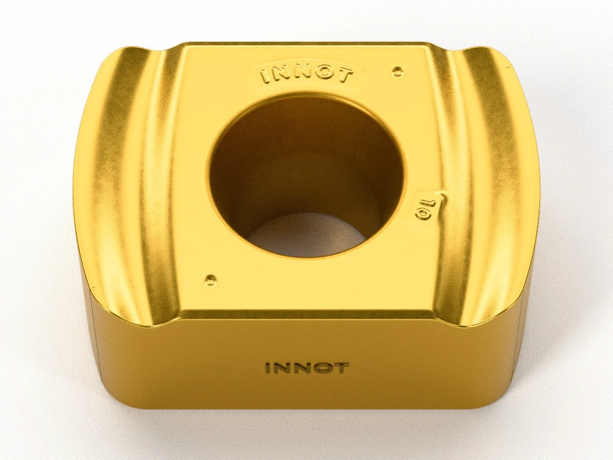
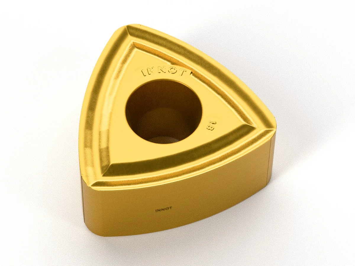
BLMP (high feed)
Double-sided insert for high-feed cutters: from BLMP 04 to 13, up to 2 mm/tooth, for steels, stainless steels, superalloys and hardened steels up to 65 HRC.
ISO P
ISO M
ISO K
ISO S
ISO H
High feed
Roughing
★ IT5220 · IT7240 · IT5210
Technical data sheet PDFCutting data, sizes and grades
Want to try it first? Request a free tester

Description
Specifications
| Code | INSL | W1 | S | RE | APMX | fz (mm/tooth) | Cutting edges |
|---|---|---|---|---|---|---|---|
| BLMP0402R-M | 6 | 4.2 | 2.52 | 0.5 | 0.5 | 0.2–1.0 | 4 |
| BLMP0402R-ML | 6 | 4.2 | 2.52 | 0.5 | 0.5 | 0.2–0.8 | 4 |
| BLMP0603R-M | 9 | 6.39 | 3.73 | 1 | 1 | 0.3–1.2 | 4 |
| BLMP0603R-ML | 9 | 6.39 | 3.73 | 1 | 1 | 0.2–1.0 | 4 |
| BLMP0603R-MM | 9 | 6.39 | 3.73 | 1 | 1 | 0.3–1.0 | 4 |
| BLMP0904R-M | 11.94 | 9.2 | 4.79 | 1.2 | 1.5 | 0.3–1.3 | 4 |
| BLMP0904R-ML | 11.94 | 9.2 | 4.79 | 1.2 | 1.5 | 0.3–1.0 | 4 |
| BLMP0904R-MM | 11.94 | 9.2 | 4.79 | 1.2 | 1.5 | 0.3–1.1 | 4 |
| BLMP1105R-M | 14.6 | 11.2 | 6.54 | 1.3 | 2 | 0.3–1.5 | 4 |
| BLMP1105R-ML | 14.6 | 11.2 | 6.54 | 1.3 | 2 | 0.3–1.2 | 4 |
| BLMP1306R-M | 12.3 | 12.3 | 7 | 1.8 | 2 | 0.4–2.0 | 6 |
| BLMP1306R-MM | 12.3 | 12.3 | 7 | 1.8 | 2 | 0.4–1.6 | 6 |
| BLMP1306R-MR | 12.3 | 12.3 | 7 | 1.8 | 2 | 0.5–2.0 | 6 |
Dimensions in mm. INSL = insert length (IC for the trigon 13), W1 = width, S = thickness, RE = corner radius, APMX = maximum depth of cut, fz = feed per tooth range.
Geometries
| Geometry | Cutting edge | Application | Sizes |
|---|---|---|---|
| M | Universal, reinforced | Steels, cast irons and hardened steels: the standard choice for roughing moulds and pockets | 04 · 06 · 09 · 11 · 13 |
| ML | Positive and sharp | Stainless steels, superalloys and work-hardening materials; low-power machines and long overhangs | 04 · 06 · 09 · 11 |
| MM | Positive, protected cutting edge | Stainless steels and titanium alloys: smooth cutting with good edge strength | 06 · 09 · 13 |
| MR | Heavily reinforced | Heavy roughing, casting and forging skins, interrupted cuts | 13 |
Technical data
| Operation | Milling – High feed: face milling, pockets, contouring, ramping and helical interpolation |
| Shape | Double-sided with convex cutting edges: 4 cutting edges per insert (6 on the trigon 13) |
| ISO material | P (steels), M (stainless steels), K (cast irons), S (superalloys and titanium), H (hardened steels) |
| Features | The convex cutting edge with a small lead angle thins the chip: you work with very high feed per tooth (up to 2 mm/tooth) and light cuts, with the forces directed along the spindle axis. Reduced vibration even with long overhangs and hardened steels up to 65 HRC. |
| Compatible cutters | INNOT modular heads, shank end mills and shell mills for BLMP (see below). Already have a cutter? Send us the code and we will check compatibility. |
How many inserts per cutter diameter
Maximum number of inserts (effective cutting edges) per cutter diameter: more inserts = more feed per minute; fewer inserts = more chip space and less power required.
| Cutter Ø | BLMP 04 | BLMP 06 | BLMP 09 | BLMP 11 | BLMP 13 |
|---|---|---|---|---|---|
| Ø10 | 2 | – | – | – | – |
| Ø11 | 2 | – | – | – | – |
| Ø12 | 3 | – | – | – | – |
| Ø13 | 3 | – | – | – | – |
| Ø16 | 4 | 2 | – | – | – |
| Ø17 | 4 | – | – | – | – |
| Ø18 | – | 2 | – | – | – |
| Ø20 | 5 | 3 | – | – | – |
| Ø21 | – | 3 | – | – | – |
| Ø22 | – | 3 | – | – | – |
| Ø25 | 7 | 4 | 3 | – | – |
| Ø26 | – | 4 | 3 | – | – |
| Ø30 | – | 5 | 3 | 2 | – |
| Ø32 | 8 | 5 | 4 | 2 | 2 |
| Ø33 | – | 5 | 4 | 2 | 2 |
| Ø35 | – | 5 | 4 | 3 | 2 |
| Ø40 | – | 6 | 5 | 3 | 3 |
| Ø42 | – | 6 | 5 | 3 | 3 |
Modular heads for BLMP
Heads with M6–M16 threaded connection to mount on carbide or steel extensions: change heads in seconds and keep the same extension.
BLMP 04 insert – heads from Ø10 to Ø32 mm
| Cutter Ø DCX | Cutting edges Z | Connection | Connection Ø DCONMS | LF | OAL | APMX |
|---|---|---|---|---|---|---|
| Ø10 | 2 | M6 | 9.7 | 17 | 31.5 | 0.5 |
| Ø11 | 2 | M6 | 9.7 | 17 | 31.5 | 0.5 |
| Ø12 | 3 | M6 | 11 | 17 | 31.5 | 0.5 |
| Ø13 | 3 | M6 | 11 | 17 | 31.5 | 0.5 |
| Ø16 | 4 | M8 | 13 | 23 | 40.5 | 0.5 |
| Ø17 | 4 | M8 | 13 | 23 | 40.5 | 0.5 |
| Ø20 | 5 | M10 | 18 | 23 | 43 | 0.5 |
| Ø25 | 7 | M12 | 21 | 27 | 49 | 0.5 |
| Ø32 | 8 | M16 | 29 | 27 | 52 | 0.5 |
BLMP 06 insert – heads from Ø16 to Ø42 mm
| Cutter Ø DCX | Cutting edges Z | Connection | Connection Ø DCONMS | LF | OAL | APMX |
|---|---|---|---|---|---|---|
| Ø16 | 2 | M8 | 13 | 25 | 42.5 | 0.7 |
| Ø18 | 2 | M8 | 13 | 25 | 42.5 | 0.7 |
| Ø20 | 2 | M10 | 18 | 30 | 50 | 1 |
| Ø20 | 3 | M10 | 18 | 30 | 50 | 1 |
| Ø21 | 3 | M10 | 18 | 30 | 50 | 1 |
| Ø22 | 3 | M10 | 18 | 30 | 50 | 1 |
| Ø25 | 3 | M12 | 21 | 35 | 57 | 1 |
| Ø25 | 4 | M12 | 21 | 35 | 57 | 1 |
| Ø26 | 3 | M12 | 21 | 35 | 57 | 1 |
| Ø26 | 4 | M12 | 21 | 35 | 57 | 1 |
| Ø30 | 5 | M16 | 29 | 40 | 65 | 1 |
| Ø32 | 4 | M16 | 29 | 40 | 65 | 1 |
| Ø32 | 5 | M16 | 29 | 40 | 65 | 1 |
| Ø33 | 4 | M16 | 29 | 40 | 65 | 1 |
| Ø33 | 5 | M16 | 29 | 40 | 65 | 1 |
| Ø35 | 4 | M16 | 29 | 43 | 68 | 1 |
| Ø35 | 5 | M16 | 29 | 43 | 68 | 1 |
| Ø40 | 6 | M16 | 29 | 43 | 68 | 1 |
| Ø42 | 5 | M16 | 29 | 43 | 68 | 1 |
| Ø42 | 6 | M16 | 29 | 43 | 68 | 1 |
BLMP 09 insert – heads from Ø25 to Ø42 mm
| Cutter Ø DCX | Cutting edges Z | Connection | Connection Ø DCONMS | LF | OAL | APMX |
|---|---|---|---|---|---|---|
| Ø25 | 2 | M12 | 21 | 35 | 57 | 1.5 |
| Ø25 | 3 | M12 | 21 | 35 | 57 | 1.5 |
| Ø26 | 3 | M12 | 21 | 35 | 57 | 1.5 |
| Ø30 | 3 | M16 | 29 | 43 | 68 | 1.5 |
| Ø32 | 3 | M16 | 29 | 43 | 68 | 1.5 |
| Ø32 | 4 | M16 | 29 | 43 | 68 | 1.5 |
| Ø33 | 4 | M16 | 29 | 43 | 68 | 1.5 |
| Ø35 | 3 | M16 | 29 | 43 | 68 | 1.5 |
| Ø35 | 4 | M16 | 29 | 43 | 68 | 1.5 |
| Ø40 | 4 | M16 | 29 | 43 | 68 | 1.5 |
| Ø40 | 5 | M16 | 29 | 43 | 68 | 1.5 |
| Ø42 | 3 | M16 | 29 | 43 | 68 | 1.5 |
| Ø42 | 5 | M16 | 29 | 43 | 68 | 1.5 |
BLMP 11 insert – heads from Ø30 to Ø42 mm
| Cutter Ø DCX | Cutting edges Z | Connection | Connection Ø DCONMS | LF | OAL | APMX |
|---|---|---|---|---|---|---|
| Ø30 | 2 | M16 | 29 | 43 | 68 | 2 |
| Ø32 | 2 | M16 | 29 | 43 | 68 | 2 |
| Ø33 | 2 | M16 | 29 | 43 | 68 | 2 |
| Ø35 | 3 | M16 | 29 | 43 | 68 | 2 |
| Ø40 | 3 | M16 | 29 | 43 | 68 | 2 |
| Ø42 | 3 | M16 | 29 | 43 | 68 | 2 |
BLMP 13 insert – heads from Ø32 to Ø42 mm
| Cutter Ø DCX | Cutting edges Z | Connection | Connection Ø DCONMS | LF | OAL | APMX |
|---|---|---|---|---|---|---|
| Ø32 | 2 | M16 | 29 | 50 | 75 | 2 |
| Ø33 | 2 | M16 | 29 | 50 | 75 | 2 |
| Ø35 | 2 | M16 | 29 | 50 | 75 | 2 |
| Ø40 | 3 | M16 | 29 | 50 | 75 | 2 |
| Ø42 | 3 | M16 | 29 | 50 | 75 | 2 |
Dimensions in mm according to ISO 13399. DCX = cutting diameter, Z = number of inserts (effective cutting edges), DCONMS = machine-side connection diameter, LF = functional length, OAL = overall length, APMX = maximum depth of cut. All heads have internal coolant.
Shank end mills and shell mills
| Insert | Shank: cutter Ø | Z | Shank Ø | Shell mill: cutter Ø | Z | Bore Ø |
|---|---|---|---|---|---|---|
| BLMP 04 | Ø8–21 | 1–5 | Ø8–20 | – | – | – |
| BLMP 06 | Ø16–40 | 2–6 | Ø16–32 | Ø32–66 | 4–9 | 16–27 |
| BLMP 09 | Ø25–40 | 2–5 | Ø25–32 | Ø32–125 | 4–14 | 16–40 |
| BLMP 11 | Ø30–40 | 2–4 | Ø32 | Ø40–200 | 4–12 | 16–60 |
| BLMP 13 | Ø32–40 | 2–3 | Ø32 | Ø40–250 | 3–11 | 16–60 |
Cylindrical or Weldon shank end mills in short, long and extra-long versions; shell mills with normal, close and extra-close pitch. Full dimensions on request.
Available INNOT grades
| Grade | ISO | Coating | Composition | Application |
|---|---|---|---|---|
| IT5220 ★ | P · M · K | PVD | AlTiN + TiSiN | Universal grade for steels, stainless steels and cast irons up to 40–50 HRC. Double-layer coating: strength, toughness and protection against edge chipping. |
| IT7240 ★ | M · S | PVD | AlCrN | Milling of difficult materials: stainless steels, superalloys and titanium. High hot hardness, high toughness and resistance to fatigue fracture. |
| IT5210 ★ | P · H | PVD | AlTiN + TiSiN | Milling of hardened steels 50–65 HRC. Coating with high thermal stability and oxidation resistance: withstands the most severe cutting temperatures. |
| IT6130 | P · K | CVD | TiN + MT-TiCN + Al₂O₃ | Semi-finishing and roughing of steels and cast irons. High-strength composite coating that balances wear and toughness; post-coating treatment increases insert toughness. |
| IT7140 | M · S | PVD | AlCrN | Milling of stainless steels, titanium alloys and superalloys. Substrate with special micro-elements: excellent toughness and high-temperature performance. |
| IT5110 | P · H | PVD | TiAlN + CrAlN + TiSiN | Milling of hardened steels 45–55 HRC. Nano-composite coating on an ultra-fine grain substrate: smooth surface, low friction, high nano-hardness and excellent oxidation resistance. |
★ Recommended grade. Other grades are available on request.
Recommended cutting data
High feed – cutting speed and feed per tooth
| Material | Hardness | Grade | Vc (m/min) | fz 04 | fz 06 | fz 09 | fz 11 | fz 13 |
|---|---|---|---|---|---|---|---|---|
| P Non-alloy / mild steel | ≤ 180 HB | IT5220 IT6130 |
200 (160–250) | 0.6 | 0.8 | 1 | 1.1 | 1.4 |
| P Alloy / quenched and tempered steel | 180–280 HB | IT5220 IT6130 |
170 (140–210) | 0.5 | 0.7 | 0.9 | 1 | 1.2 |
| P Tool and mould steel | 280–350 HB | IT5220 IT5110 |
150 (120–180) | 0.4 | 0.6 | 0.8 | 0.9 | 1 |
| M Stainless steel | ≤ 270 HB | IT7240 IT7140 |
140 (110–180) | 0.4 | 0.5 | 0.7 | 0.8 | 1 |
| K Grey and ductile cast iron | 180–260 HB | IT6130 IT5220 |
180 (140–240) | 0.6 | 0.8 | 1 | 1.1 | 1.4 |
| S Titanium alloys | ≤ 350 HB | IT7240 IT7140 |
60 (40–80) | 0.3 | 0.4 | 0.5 | 0.6 | 0.8 |
| S Nickel / cobalt-based superalloys | ≤ 400 HB | IT7240 | 35 (25–50) | 0.25 | 0.3 | 0.4 | 0.5 | 0.6 |
| H Hardened steels | 45–55 HRC | IT5210 IT5110 |
100 (70–130) | 0.3 | 0.4 | 0.5 | 0.6 | 0.7 |
| H Hardened steels | 55–65 HRC | IT5210 | 60 (40–80) | 0.2 | 0.3 | 0.4 | 0.4 | 0.5 |
Guide values for dry milling or with air, ap up to APMX (hardened steels: ap ≤ 50% of APMX). Vc: recommended (min–max range); fz in mm/tooth per insert size. Reduce fz by 20–30% with overhangs over 4×D, when ramping and in helical interpolation.
Need a complete high-feed cutter?
Tell us diameter, connection and material: we propose a head or cutter, inserts and grade, with cutting data calculated for your part.
You may also like
RDMW / RDKW
RPKT / RPMT-SM
SDMT / SDMW
RDHX (15° round)
RCKT-FM
Recently viewed
RPMT-HM / RPMW